Ferrite Magnets
Ferrite Magnets

Item specifics

Material
Sintered Ferrite Magnets
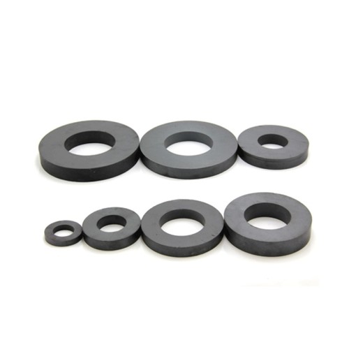
Shape
Main Disc, but Block or Rectangular or Cuboid, Ring, Cylinder, Arc and Irregular shape are also available
Magnetized direction
Axially or Diametrical Magnetized, but Thickness, Multipoles and Radial magnetization are also available
Certificate
ISO/TS 16949, ISO9001, ISO14001, RoHS, REACH
Packing
Standard sea or air packing, such as carton, wooden box, pallet etc.
Transportation
courier (TNT, DHL, FedEx, UPS), air or sea.

Review

Description

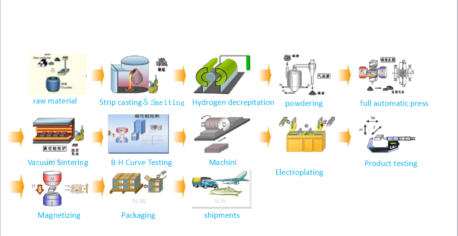
Since the 1950s, hard ferrite (ceramic) magnets have been widely applied because of low cost, good magnetic properties and excellent environmental stability. Both isotropic and anisotropic hard ferrite magnets are available for Cinfer. The magnetic energy products of anisotropic hard ferrite magnets are higher than that of the isotropic hard ferrite magents by up to 300%. Depending on the base materials, there are Barium Ferrite and Strontium Ferrite with higher coercive. After preliminary inspection, the raw materials (mainly iron oxide, strontium carbonate) are weighed, blended, pre-sintered and milled to fine powders with hexagonal crystals. For isotropic magnets, the pre-materials are milled to powders and then pressed. For anisotropic magnets there are two procedures in the production, dry press and wet press. Firstly, the raw materials are dried and then pressed in a magnetic field. Secondly, the raw materials are wet pressed under the influence of a magnetic field, then followed by sintering, finishing cleaning and magnetization. Finally the surface can be machined, marked, magnetized or coated according to customers' requirements.

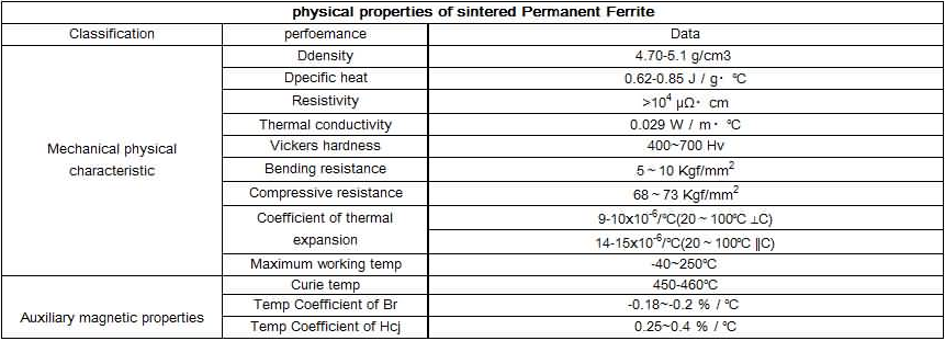
Ceramic magnets are very hard and brittle, consequently machining must be done with a diamond wheel, and is easier when done prior to magnetization. Standard tolerances for ceramic magnet dimensions are +/-.005″ for ground dimensions and +/- 2% of feature size for dimensions. Because of their brittleness these magnets will not withstand impact or flexing. We recommend that they not be used for structural purposes.Ceramic magnets are chemically inert non-conductors, which is a benefit in many applications according to different grade as below

Maximum operating temperature for a ceramic magnet is 250°C. Although you will experience magnetic losses when operating at elevated temperatures, the losses are recovered when the material is brought down to normal ambient temperature. However, operating in very cold temperatures (-20°C) can result in permanent losses of magnetic strength unless the circuit has been designed for such extremes.

Pros:

1. least expensive material compared to alnico magnets or rare earth magnets

2. High intrinsic coercive force

3. Corrosion resistance 

烧结铁氧体性能表


Sintered Hard Ferrite Magnetic Property Table

牌号

Grade

剩磁 Br

Residual Induction

磁感矫顽力 HcB

Coercive Force

内禀矫顽力 Hcj

Intrinsic Coercive Force

最大磁能积 (BH)max

Maximum Energy Products

Other Equivalent (Reference Only)

mT

kGs

KA/m

KOe

KA/m

KOe

KJ/m3

MGOe


min


max

min


max

min

max

min


max

min

max

min


max

min


max

min


max


Y8T

200


235

2.00


2.35

125

160

1.57


2.01

210

280

2.64


3.51

6.50


9.50

0.80


1.20

HF8/22, C1, FB1A


Y22H

310


360

3.10


3.60

220

250

2.76


3.14

280

320

3.51


4.02

20.00


24.00

2.50


3.00

HF20/28


Y25

360


400

3.60


4.00

135

170

1.70


2.14

140

200

1.76


2.51

22.50


28.00

2.80


3.50

HF25/14


Y26H-1

360


390

3.60


3.90

200

250

2.51


3.14

225

255

2.83


3.20

23.00


28.00

2.90


3.50

HF25/22


Y26H-2

360


380

3.60


3.80

263

288

3.30


3.62

318

350

3.99


4.40

24.00


28.00

3.00


3.50

HF24/35, C9, PMF-2BB, C7


Y27H

350


380

3.50


3.80

225

240

2.83


3.01

235

260

2.95


3.27

25.00


29.00

3.10


3.60

HF22/30


Y28

370


400

3.70


4.00

175

210

2.20


3.64

180

220

2.26


2.76

26.00


30.00

3.30


3.80

HF26/18, C5


Y28H-1

380


400

3.80


4.00

240

260

3.01


3.27

250

280

3.14


3.52

27.00


30.00

3.40


3.80

FB4B, C10


Y28H-2

360


380

3.60


3.80

271

295

3.40


3.70

382

405

4.80


5.08

26.00


30.00

3.30


3.80

FB6E, PMF-2BF


Y30H-1

380


400

3.80


4.00

230

275

2.89


3.46

235

290

2.95


3.64

27.00


32.50

3.40


4.10

HF26/26, C8, PMF-2BD


Y30H-2

395


415

3.95


4.15

275

300

3.45


3.77

310

335

3.89


4.20

27.00


32.00

3.40


4.00

HF26/30, PMF-2BE, FB5H, C12, PMF-5BE


Y32

400


420

4.00


4.20

160

190

2.01


2.39

165

195

2.07


2.45

30.00


33.50

3.80


4.20

HF32/17


Y32H-1

400


420

4.00


4.20

190

230

2.39


2.89

230

250

2.89


3.14

31.50


35.00

3.90


4.40

HF32/22, FB4D, C8B


Y32H-2

400


440

4.00


4.40

224

240

2.81


3.01

230

250

2.89


3.14

31.00


34.00

3.90


4.30

HF32/25, FB5N, PMF-7BB


Y33

410


430

4.10


4.30

220

250

2.76


3.14

225

255

2.83


3.20

31.50


35.00

3.90


4.40

C8B, PMF-2BB, FB4X, C11, PMF-6BB


Y33H

410


430

4.10


4.30

250

270

3.14


3.39

250

275

3.14


3.45

31.50


35.00

3.90


4.40

PMF-6BD, FB5B, PMF-5BD


Y34

420


440

4.20


4.40

200

230

2.51


2.89

205

235

2.57


2.95

32.50


36.00

4.10


4.40

C11, PMF-5BB


Y35

430


450

4.30


4.50

215

239

2.70


3.00

217

241

2.73


3.03

33.10


38.20

4.10


4.80

PMF-7BB


Y36

430


450

4.30


4.50

247

271

3.10


3.40

250

274

3.14


3.44

35.10


38.30

4.40


4.80

FB6N, PMF-7BD


Y38

440


460

4.40


4.60

285

305

3.58


3.83

294

310

3.69


3.89

36.60


40.60

4.60


5.10

FB9N, PMF-9BD


Y40

440


460

4.40


4.60

330

354

4.15


4.45

340

360

4.27


4.52

37.60


41.80

4.70


5.20

FB9B, PMF-9BE


Sintered Ferrite Manufacturing Process


The typical physical properties of Ferrite are given in the table below. These values must not be understood as guaranteed, as the properties are not controlled in manufacture. Ferrite magnets are fragile and must never be used as load carrying elements in a design.